R & D Spin Coater for 200 mm & 300 mm Wafers
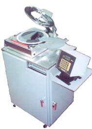
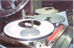
R & D spin coater for wafers up to 300 mm in diameter. Alignment system/chuck is for both the 200 mm and 300 mm wafers. This system has an edge bead removal preset for both 200 and 300 mm wafers. The bowl is 15" I.D. with a removable polyethylene liner and splash deflector. The lid is pneumatically powered. The PWM32 Microprocessor Controller has a built in PWM motor driver system. This system has a powered lid actuator, rear service connections -- compressed air, vacuum, air exhaust, and 115 vac (or optionally 220 vac) power. The PWM32 system controller is typically installed inside the cabinet, accessible behind the front door, or on an optional cantilver arm to keep controller out of operator's way and to reduce system width. The mounting arrangement of the wafer alignment disc is also visible.
 WAFER ON ALIGNMENT DISC, APPROACHING LOAD POSITION: The photo on the left shows a 200 mm wafer. The wafer will be moved to an aligned position when the alignment arm comes against a positive stop in the clockwise direction. The substrate lifter mechanism is then actuated to lift the wafer from the alignment disc. The alignment disc is then moved counter-clockwise to allow the lifter mechanism to lower the wafer to the surface of the vacuum chuck.
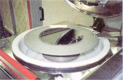 200 MM CENTERED ABOVE CHUCK: The photo to the right shows the wafer lifted from the alignment disc. The alignment arm is aligned with the spinner shaft when against a solid stop. After the wafer is lifted from the alignment disc, the disc is rotated out from under the wafer and the wafer is lowered to the vacuum chuck surface. Appropriate interlocks insure that vacuum is applied to the chuck when the wafer is lowered, to avoid wafer slippage due to an air bearing surface. Also, it is impossible to raise the lifter if vacuum is applied to the chuck. Otherwise, wafers may be broken by the lifter.
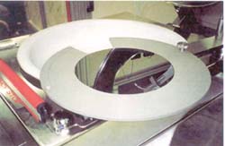
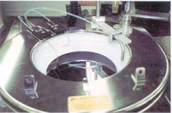
 300 MM CENTERED ABOVE CHUCK: The photo to the left shows a 300 mm wafer on the lifter, ready to be lowered into the spinner bowl. The alignment disc on the right has recesses for both the 200 and 300 mm wafers. The recesses are designed to support the wafers only at the edges with no other back-side contact. More recesses could be accommodated. Alignment discs can easily be changed. A rocker switch provides up/down control of the substrate lifter mechanism. Push button switches or a foot switch can be used to raise and lower the powered lid.
 200 MM ON LIFTER - TOP ANGLED VIEW: This view on the right shows a 200 mm wafer that has been transferred from the alignment disc to the wafer lifter, and then the alignment disc has been moved out from under the wafer. The wafer lifter operates through the spinner motor shaft. The powered lid is open.
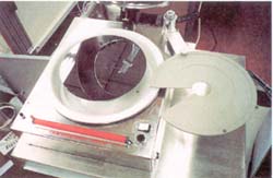
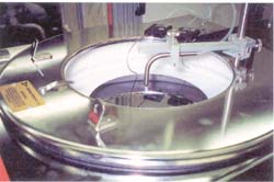
 200 MM WAFER - TOP VIEW: This photo on the left is a stationary view showing a 200 mm wafer on the chuck. The dispense line is positioned to one side of the wafer. It would be moved to the center position for dispensing (manual movement in this system). Two small dispense lines for edge bead removal are visible, one for 200 mm and one for 300 mm wafers. The line for edge bead removal on the 200 mm wafer is lined up with the edge of the wafer. A valve switches between the 200 and 300 mm edge bead removal lines. Brackets for a plastic shield between the operator and spinning substrate are visible on the top/front of the powered lid.
 LID CLOSED - TOP VIEW: This view (photo on the right) shows a 200 mm wafer on the spinner chuck. The powered lid is closed and the photo resist dispense line is positioned over the center of the wafer, in the stationary dispense position. A powered moving arm is available for dispensing with the arm moving at a programmed rate, either for dispensing while moving inward or outward. Two edge bead removal lines are visible. Brackets for a plastic shield between the operator and spinning substrate is shown on the top front of the lid.